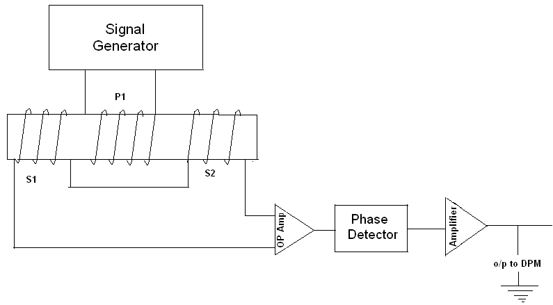
 The primary is excited by an A.C voltage of frequency 50Hz to 20KHz. The secondary are connected in series opposing when the core is placed in the null position and the output voltage is zero as equal voltages induced in the secondary cancel each other.
LVDT primary, secondary windings are connected such that applied voltage on primary and induced voltage on secondary are 180° phase opposition as shown in the figure. If the core is moved to the left of null position more flux will link S1 than that of S2. A resultant voltage (Es1 – Es2) which is in phase with primary voltage will appear across the output.
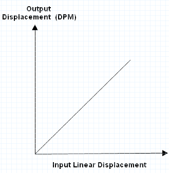
If the core is moved to the right of null position, the resultant voltage (Es1 – Es2) is 180° out of phase with primary voltage which will be the output. Thus the output voltage is a measure of displacement. The variation of output voltage with the displacement is as shown below:
Linear Variable Differential Transformer(LVDT) has the advantage of having high sensitivity, high range, ruggedness, low hysteresis, and low power consumption.
Procedure for finding the characteristics of LVDT:-
- Connect the terminals marked “Primary” on the DPM to the terminals marked “Primary” on LVDT transformer.
- Similarly connect “secondary” terminals on the DPM to the “secondary” terminals on LVDT
- Keep the pot (P1) in “MAX” in the post anti-clockwise position.
- Caliberation of DPM:- The magnetic core is so positioned that the pointer is indicating zero position. If the DPM is not indicating zero, rotate the plot ‘MN’ to zero to get a zero on DPM. Now displace the core 19mm position in one of the directions. Adjust the ‘MAX’ plot to get an indication of 19.00 on DPM.
- Now displace the core by a small amount in range of ±19mm and note the scale readings and DPM readings.
- Draw the graph of input displacement on X-axis and output displacement of Y-axis. The expected waveform is as follows:

Precautions to be taken for this experiment are
- While connecting the terminals on DPM to transducer follow the color code carefully.
- Move the LVDT core in a gentle fashion by operating the knob for more movements.
I discovered your Characteristics of LVDT – Linear Variable Differential Transformer page from Google Search and noticed it is getting quiet a lot lot of hits daily. Thanks for this useful info on Characteristics of LVDT